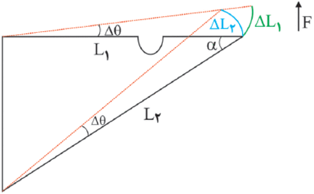
Figure 5.
Schematic and exaggerated illustration of the role of tension in a bracing element. F: mesially directed force, L1: length of the bar, L2: length of bracing system, Δθ: angular change which is very small, ΔL1: linear change at the present of bracing element, ΔL2: linear change when bracing element is not active and whole system is under rotation to H point, and H − H′: differential length change in L2 when tension created.


